Introduction
A MUX flip-flop, short for multiplexer flip-flop, combines the functionalities of multiplexer (MUX) and flip-flop circuits to enhance data storage and processing capabilities in digital electronics. Essentially, it enables the selection and control of multiple data inputs for a single output while maintaining the state of the data across clock cycles. MUX flip-flops are commonly utilized in various digital systems, including register storage, data routing, and state machines, owing to their ability to improve circuit efficiency and reduce the number of required components. This article delves into the workings of MUX flip-flops, examining their designs, applications, and inherent advantages over traditional circuits.
Understanding MUX and Flip-Flops
Before diving into mux flip-flops, it’s essential to understand the basic concepts of multiplexers (MUX) and flip-flops.
Multiplexer (MUX)
A multiplexer is a combinational circuit that selects one of many inputs and forwards the selected input to a single output line. The selection of inputs is controlled by a set of select lines. The primary function of a MUX is to enable efficient data routing and selection in digital systems, making it invaluable in applications such as multiplexed communication systems and digital signal processing.
Flip-Flops
Flip-flops are memory elements used to store binary data. They are bistable devices, meaning they can exist in one of two states: a logic high (1) or logic low (0). Flip-flops are widely used in sequential circuits to store data bits, perform counting operations, and maintain state in various applications. The most common types of flip-flops include D (Data), T (Toggle), JK, and SR (Set-Reset) flip-flops. Each has unique input and timing characteristics that make them suitable for different applications.
What is a MUX Flip-Flop?
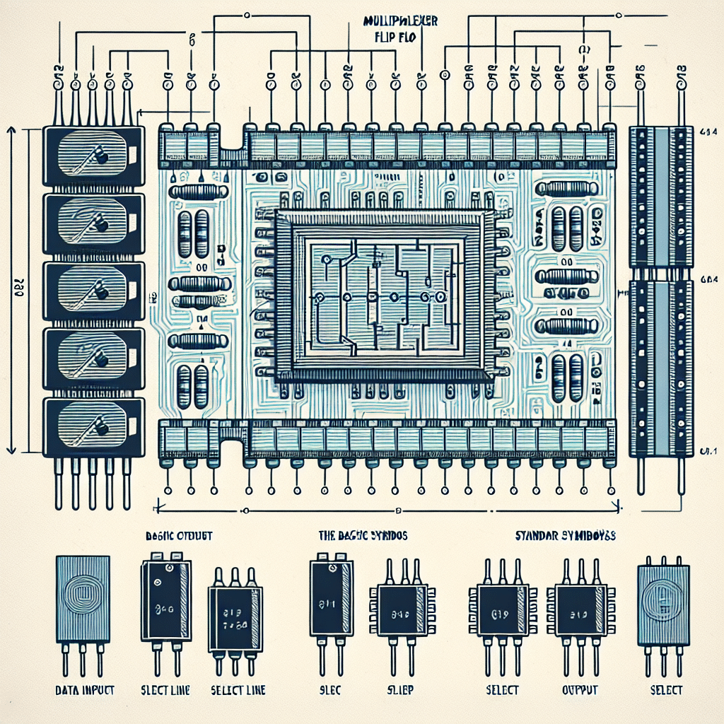
A MUX flip-flop is a digital circuit that integrates the features of a multiplexer with those of a flip-flop. Its primary purpose is to select data inputs controlled by the multiplexer circuits while retaining the selected data’s state, similar to how a traditional flip-flop operates. The architecture of a MUX flip-flop typically consists of data inputs, a clock signal, select lines, and a feedback mechanism that stores the output state.
How MUX Flip-Flops Work
The operation of a MUX flip-flop can be broken down into several key components and processes:
Architecture
The architecture of a MUX flip-flop can be seen as a MUX feeding into a D flip-flop. The multiplexer receives multiple data inputs, and based on the select lines, it chooses one input to pass through to the D flip-flop. The chosen input value is then stored in the flip-flop during the clock cycle, thus behaving similarly to a typical flip-flop. This way, the MUX flip-flop can selectively store data from different sources efficiently.
Operation
The operation of a MUX flip-flop involves two primary phases: selection and storage.
- Selection Phase: When the select lines are enabled, the MUX determines which of the multiple inputs is to be forwarded to the flip-flop. Only one of the data inputs can be selected at any given time.
- Storage Phase: Once the MUX has determined the selected input data, the D flip-flop will capture this data on the active edge of the clock signal (typically the rising edge). This action locks the state of the selected input until the next clock cycle, creating a stable output.
Timing Diagrams
Timing diagrams can help visualize the operation of a MUX flip-flop. They demonstrate the relationship between the select lines, data inputs, clock signal, and the output state. Analyzing timing diagrams is crucial for understanding the potential delays and setup times required for reliable operation.
Applications of MUX Flip-Flops
Knowing the applications of MUX flip-flops can help illustrate their importance in modern digital designs. Here are some common use cases:
Data Routing
In data routing circuits, MUX flip-flops enable efficient selection of data paths, allowing systems to dynamically change data sources based on control signals. This is particularly useful in communication systems where multiple data streams need to be processed.
Register File Design
MUX flip-flops are often implemented within register files that temporarily store data in processors. The design provides a means for selecting data from multiple registers while maintaining state and functionality. This enhances data throughput and operational efficiency in computing architectures.
State Machines
Digital state machines frequently use MUX flip-flops to manage various states and state transitions. By effectively selecting different data paths under specific conditions, MUX flip-flops facilitate complex logic decisions in sequential circuits.
Advantages of Using MUX Flip-Flops
Several benefits make MUX flip-flops a favored choice in digital circuit design:
Efficiency
By integrating the functions of a multiplexer and a flip-flop, these circuits reduce the total number of components required in a design. This can lead to more compact circuit layouts and decreased production costs.
Flexibility
MUX flip-flops offer the flexibility to switch between multiple data sources dynamically. This adaptability is valuable in systems where data inputs change frequently, making it easier to accommodate various operational modes without modifying hardware.
Improved Timing
Through the straightforward architecture of MUX flip-flops, designs can achieve faster operational speeds compared to conventional circuits. Reduced component count can minimize propagation delays and improve overall system performance.
Counterarguments: Limitations of MUX Flip-Flops
It is also important to consider some limitations of MUX flip-flops:
Complexity in Design
The integration of multiplexer and flip-flop functions can introduce complexity in circuit design and analysis. For simpler applications, implementing distinct components may be more straightforward and easier to troubleshoot.
Power Consumption
In high-frequency applications, MUX flip-flops may consume more power due to the constant switching of the multiplexer components. Careful power management practices must be applied to mitigate potential excess energy consumption.
Conclusion
MUX flip-flops represent a significant advancement in digital circuit design, streamlining operations by merging the functionalities of multiplexers and flip-flops into a single versatile component. As you explore the potential for implementing MUX flip-flops in your designs, consider both their profound advantages and inherent limitations to achieve a balanced and effective approach to digital architecture.
FAQs
1. What is the primary function of a mux flip-flop?
Its primary function is to select one of multiple data inputs and hold its state across clock cycles, combining the roles of a multiplexer and a flip-flop.
2. How does a mux flip-flop differ from a traditional flip-flop?
A traditional flip-flop only stores a single input, while a mux flip-flop can select from multiple inputs before storing them, offering more versatility in data routing and storage.
3. What are the typical applications of mux flip-flops?
They are typically used in data routing, register file designs, and state machines, enhancing data selection and storage capabilities in digital systems.
4. Are there any downsides to using mux flip-flops?
Yes, while they are efficient, mux flip-flops can introduce design complexity and may consume more power in high-frequency applications.
5. What should I consider when integrating mux flip-flops into my design?
Consider your application’s requirements, the potential benefits of using integrated components, and the trade-offs regarding complexity and power consumption.


